A Part Is Never Alone: Designing Components That Respect Their Connections
How two new methods from Autodesk Research let a component’s shape evolve freely, while the joints that hold the assembly together stay exactly where they need to be
Have you ever run an optimizer on a bracket, loved the organic result it gave you, and then realized the beautiful new shape no longer fits the pin, bolt pattern, or weld it was supposed to mate with? If so, you have run into one of the quiet, stubborn problems of computational design: our best shape-changing tools tend to treat geometry like clay, while the real world treats certain features as sacred.
A structural part almost never works in isolation. It lives inside an assembly, and it earns its keep by talking to its neighbors through interfaces: the pin holes, bearing seats, mounting pads, and welded faces that carry load and permit motion. A revolute joint has to stay cylindrical or it cannot rotate. A welded face has to stay flat or it cannot be manufactured or transfer load cleanly. Distort those features and the part becomes, quite literally, useless, no matter how good its stress numbers look.
You can see this everywhere once you start looking. Think of a simple pair of pliers: the two handles are free to be any shape a designer likes, but the pivot hole where they meet must stay round, or the pin binds and the tool stops working. The same is true of the rocker in the vehicle suspension above. Its job is to shuttle load from the wheel to the chassis, and it can only do that if every one of its pin joints stays true to the parts it connects.
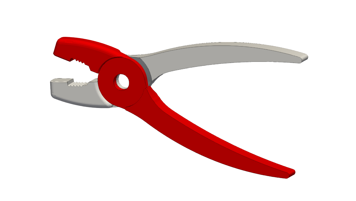
The everyday version of the same rule: the handles can change shape, but the pivot hole must remain circular.
This is the thread that ties together two recent papers from our team, both published in Computers and Structures. They attack the problem from two different directions, but they tell one story: let the free part of a shape be free, and keep the functional part functional. The first paper reinvents a component’s shape from scratch with topology optimization. The second lets you smoothly explore variations of an existing shape and simulate them almost instantly. In both, the joints are treated as first-class citizens, not afterthoughts.
To make the point concrete, here is what happens when you don’t respect the interfaces. Below, the same suspension rocker is deformed by a standard shape-warping method. On the left, the large cylindrical bore collapses into an oval and the mesh around the joints becomes badly skewed; the joint is now geometrically incompatible with the assembly. On the right is what we want instead: the surrounding body deforms freely, but every joint keeps its exact circular cross-section.
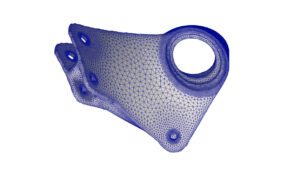
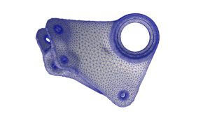
Warp the rocker naively (left) and the large cylindrical bore collapses into an oval while the mesh around the joints skews badly, the joint no longer fits the assembly. With feature preservation (right) the body twists just as much, but the bore and every pin keep their exact circular cross-section.
That contrast, distortion versus preservation, is the whole game. Here is how we win it, twice.
Act One: Growing the optimal shape without breaking the joints
Topology optimization is the tool behind those bone-like generative designs you have probably seen: you specify loads, supports, and how much material you are allowed, and an algorithm grows the stiffest possible structure. We use a flavor called level-set topology optimization, where the shape is represented implicitly (as the boundary between “material” and “no material”) and is nudged, iteration by iteration, in whatever direction lowers the objective.
The catch is exactly the one above. The standard recipe either freezes the interface regions completely, so they cannot adapt at all, or lets them evolve freely and destroys them. Neither is what an engineer wants. In practice, you often don’t know the best place for a pin, or its ideal radius, or the exact angle a mounting face should sit at. You want the optimizer to figure that out too, but only within the bounds of what keeps the feature valid.
Our first paper, An interface-preserving level set update strategy for topology optimization of mechanical assemblies, solves this with a new update rule we call the Constrained Hilbert Space Extension (C-HSE) method. The idea, in plain terms:
- Everywhere except the interfaces, the boundary moves freely, the usual free-form topology optimization that produces those efficient, organic shapes.
- Inside each interface region, the shape is only allowed to move by “rigid-body-like” motions: translation, rotation, and scaling. A cylinder can slide, tilt, grow in radius, or lengthen, but it stays a cylinder. A flat weld face can move and resize, but stays flat.
- Crucially, the two are stitched together into a single, smooth update that is still guaranteed to improve the design. Mathematically, we build the update velocity by solving a small constrained optimization problem in a thin band around the boundary, so the combined motion is provably a descent direction for the objective. The joints are preserved by construction, not by a fix-up applied afterward.
The result is an optimizer that co-designs the body and the placement of the interfaces at the same time. Take this L-bracket. It has to support a load through a pin hole, avoid a keep-out zone, and use only a fraction of its original material. The optimizer carves away everything it can, while the loaded pin hole stays perfectly circular and is free to migrate and resize to the spot that minimizes compliance (green shows the original envelope).
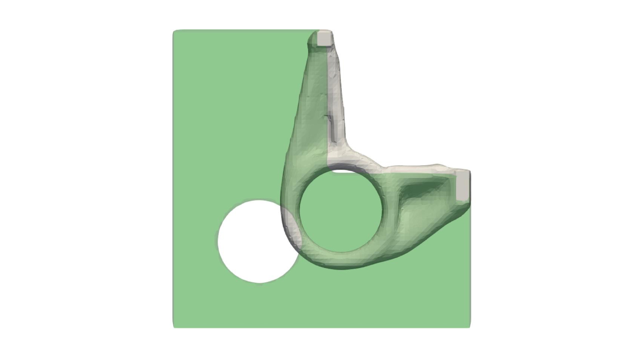
An L-bracket after optimization (green shows the starting envelope). The structure is free-form, but the load-bearing pin hole stayed perfectly circular, and the optimizer chose its best size and location.
And here is the payoff on the component we care about most, the suspension rocker. The optimizer generated an efficient, free-form body while keeping all of its joint interfaces cylindrical, and even rotated one of them to line up better with the force it carries. The views below tell that story from a few angles.
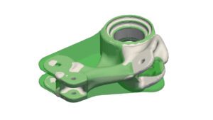
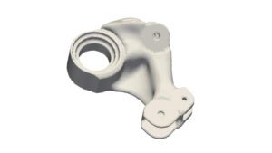
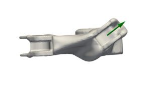
The optimized rocker (white) carved out of its original envelope (green). The body is entirely free-form, but the joints are left untouched. The green arrow shows the direction of the applied load. The optimizer was free to rotate this joint, and it swung it around to line up almost exactly with the force it has to carry.
Act Two: Exploring and simulating variations, at interactive speed
Optimizing a shape from scratch is one mode of design. The other, the one engineers spend most of their day in, is iterating: tweak a parameter, check the stress, tweak again. The problem is that every geometric tweak normally means re-meshing and re-running a full finite element (FE) simulation, which is far too slow for the interactive, many-query workflows designers actually want.
Our second paper, Hierarchical free-form deformation with rigid feature preservation for shape-parameterized model order reduction, tackles both halves of that problem, the geometry and the speed, and it preserves the same interfaces while doing so.
The geometry engine is a hierarchical free-form deformation (FFD). Picture the part wrapped in a lattice of control points; move the points and the geometry smoothly follows. We use two lattices:
- A coarse grid with only a handful of control points defines the global shape changes, bending, twisting, thinning – using just a few intuitive parameters. Fewer parameters is exactly what you want for fast exploration.
- A fine grid produces the final smooth deformation. Here is the trick that preserves the joints: for the fine control points that surround a constrained region, we don’t let them follow the coarse deformation blindly. Instead we compute the best-fit rigid (or uniformly scaled) motion for that cluster and move them by that Because the final map is a single smooth spline through these modified points, the joint comes out exactly rigid, while the transition to the free-form body stays seamless. No seams, no post-hoc corrections.
You have already seen this method at work. The rocker comparison at the top of this post is exactly it: the same twist deformation applied once without rigidization (the bore collapses) and once with it (every joint stays circular). We have applied the same approach to other components too, such as an excavator arm with four pin joints, bending the body as much as you like while each pin stays perfectly round.
Now for the speed. Once we can deform a shape this way, we build a reduced-order model (ROM) on top of it. The intuition: instead of re-solving a huge FE system for every new shape, we do a modest amount of offline homework (solving the full model for a small set of training shapes), distill the essential solution patterns, and then answer new queries in a tiny fraction of the cost. We pair this with a technique called hyperreduction that shrinks the number of points where the physics has to be evaluated.
The savings are dramatic, and the accuracy holds. For the rocker, the full model has about 812,000 degrees of freedom and 543,000 evaluation points. The reduced model needs on the order of a dozen modes and a few hundred evaluation points, a roughly 1,800× reduction in cost and tens of thousands of times fewer unknowns, all while matching the full simulation to high accuracy. That is the difference between waiting on a solver and getting an answer as fast as you can move a slider.
Why this matters
Both methods rest on the same conviction: the features that let a part do its job in an assembly are constraints to be respected, not obstacles to be optimized away. Get that right, and you unlock two capabilities that engineers have wanted for a long time:
- Optimize the part and its interfaces together. Let the algorithm find not just the best material layout, but the best location, orientation, and size of the joints, without ever producing a joint you can’t actually build or mate.
- Explore and simulate design variations at interactive speed, with a reduced-order model that stays physically meaningful because the joints never distort.
What’s next
The natural next step is to stop treating a component in isolation and design the whole assembly at once, multiple parts, each with its own evolving shape, meeting at shared interfaces, with loads flowing between them. The building blocks are now in place: a way to grow optimal shapes that keep their connections valid, and a way to deform and simulate those shapes fast enough to iterate. Point them at an assembly, let the interfaces move in lockstep across neighboring parts, and the optimizer can co-design an entire mechanism, joints and all.
Parts never work alone. It’s about time our design tools stopped pretending they do.
This work was carried out at Autodesk Research in Toronto. The topology optimization method appears in An interface-preserving level set update strategy for topology optimization of mechanical assemblies (Adrian Humphry, Mehran Ebrahimi, Nigel Morris, Adrian Butscher), and the deformation-and-model-order-reduction framework in Hierarchical free-form deformation with rigid feature preservation for shape-parameterized model order reduction (Alireza H. Razavi, Mehran Ebrahimi, Adrian Humphry, Adrian Butscher, Nigel Morris), both in Computers and Structures.
Get in touch
Have we piqued your interest? Get in touch if you’d like to learn more about Autodesk Research, our projects, people, and potential collaboration opportunities
Contact us