Can a robot design and build its own infrastructure?
What if the bridges of tomorrow were sentient? What if they interacted with their users and learned from their own experience to improve the next generation. What if the bridges of tomorrow were able to build themselves using past experience and knowledge of their surroundings. What if a robot could arrive at a river and print its way across.
At Autodesk Research, we explore new ways of designing, making, and building things. We often work with our customers to prove out these new workflows. With Dar, an international consulting organization for the Architecture, Engineering, and Construction industry, we set out to explore a new workflow for creating civil infrastructure, using technologies more familiar to the manufacturing industry.
In this three-part series, I will share the design process, the materials and sensors we used, and the manufacturing process for successfully 3D printing our 5m smart bridge.
Part 1: Design
The Story
Together with Dar, we imagined what it would take for a robot to 3D print its own infrastructure, without any human input. A bridge one click away.
We asked ourselves: If generative design can automate the design process, and industrial robots can automate manufacture, can we automate the whole workflow for infrastructure projects like bridges? How far can we push the concept?
The vision was to use Dar’s decades of experience and data from building bridges to supplement Autodesk’s knowledge in design and manufacturing. This combination of expertise would feed a design algorithm capable of producing bridge designs for any given span, ground conditions, loads, and other variables. In doing so, designs would become scalable and adaptable to meet specific site needs, while respecting any manufacturing constraints.
Materials would be local and sustainable as if grown from the ground the infrastructure lives on. Once built, the bridge would interact with users and the environment through various sensors, to understand the way it is being used. That data and understanding would be fed into the cloud and used to inform the next generation of bridge designs.
Although high in ambition, and heavy on metaphor, this story served as a North Star for our work on the project.
The Design
Our decision to print as-if in-situ came with interesting challenges. It meant that the bridge would act as a pure cantilever during printing, and as a propped cantilever after installation. These two distinct load cases were given as inputs to a generative design study in Fusion 360.
Load Case 1: Cantilever, during printing
Load Case 2: Propped cantilever, after installation
Although this double load case is a relatively novel approach for 3D printing, it is surprisingly reminiscent of an established bridge construction process – the Balanced Cantilever Method – where segments of the bridge act as cantilevers, until they connect with the next pier. Multiple load cases are also very common to see in generative design for mechanical components.
Generative Design for Additive Manufacturing
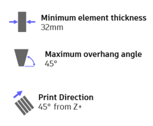
To push the current limits, we worked with our product teams to explore constraints for the generative design solver which ensure the part is manufacturable with our 3D printing setup. The ‘Manufacturing Constraints’ concept already existed for die casting and milling, where it must be physically possible to demould the part, or where all features must be reachable by a milling tool. In the case of additive manufacturing, we need to obey a minimum element thickness, a maximum overhang angle, and define the direction in which the part will be printed.
The outcome of our generative design study maintained these design requirements.
Angled Printing
The key to the vision of printing across a river is the ability to print at an angle. Instead of the traditional method of laying one layer on top of another in a vertical stack, the part is sliced at an angle that allows large distances to be spanned. But angled printing offers designers more than the hypothetical “print-across-a-river” story – it offers them tangible benefits and freedoms in reducing support structures and increasing print quality, depending on the application. If we designed a similar bridge but sliced it horizontally, a large amount of support material would be required, all of which would be wasted time and material.
With a design like this, we print many more layers, but each layer time is a lot shorter, which means we can more easily retain heat in the part before the next layer is added. Imagine the time taken to print a single flat layer 5m in length. By the time one layer is complete, the part will have already cooled, it will probably have warped in the corners, and the adhesion of the subsequent layer will be very weak. By designing parts to be printed on an angle, our layer times can be limited to minutes rather than hours.
Although it might look much more complicated, the rules we need to follow for angled printing are almost identical. To prove this point, we literally turned an Ultimaker on its side! From the perspective of the 3D Printer, nothing significant has changed. Only our frame of reference has changed.
However, on the macro level, the new direction of gravity is certainly important, meaning we needed strong adhesion to the build plate! More on that in the next article in this series.
Infill
The results of generative design are often compared to bone structures, which is somewhat accurate, given bone is the result of optimization over many generations of evolution. The difference is generative design works over a few hours rather than a few millennia. We took the bone analogy a little further in this project, using a gyroid infill pattern that loosely replicates the internal structure of bone, offering good strength at a low infill density. The flowing shape of the infill also lends itself to fast and easy printing – perfect for our needs. The only downside is curved lines require many more waypoints to describe them in robot code, so we had some very large files to load on to the robot!
Structural Simulation
Despite the generative design’s optimized result, we still conducted structural simulations to verify the final geometry should meet our requirements. Although we also used Fusion 360’s Simulation capabilities (see image), we used ANSYS software to give us industry-standard assurance of the strength.
However, additive manufacturing is not a standardized construction process, so material characteristics and anisotropy are not entirely captured in the structural simulation as standard. For that reason, we conducted a range of mechanical tests on our material. More on that in the second blog post to follow!
Peter Storey is a Research Engineer at Autodesk.
Get in touch
Have we piqued your interest? Get in touch if you’d like to learn more about Autodesk Research, our projects, people, and potential collaboration opportunities
Contact us