From Design and Break to Design and Make, Part Two
Building research value through physical prototyping
In the first part of the blog, we talked about how AI is closing the gap between early research prototypes and consumer products faster than ever before, and how testing prototypes against real-world problems can dramatically advance the research through the Technology Readiness Levels (TRLs).
Here, we put into practice these ideas through a case study, the design of a robotic gripper, to showcase the benefits of physical prototyping in research.
Finding an exemplar
Defining requirements
Our team wanted to better understand some of our research surrounding design propagation and to evaluate an assembly of parts where subtle variations in the design of components could result in significant design changes downstream. We concluded that a four-bar linkage would serve as a simple exemplar. This concept could be integrated into a robotic gripper, providing a direct connection to a real-world application.
Why a four-bar linkage?
A four-bar linkage might seem simple at first, as it’s just four connected bars forming a closed loop but, it’s a powerful mechanical building block. By reducing the system to wireframe elements, we can define its motion through joints and line lengths, making it ideal for simulation and optimization. Our challenge was clear: design and optimize a robotic gripper finger that not only functions efficiently but meets every aspect of the design brief.
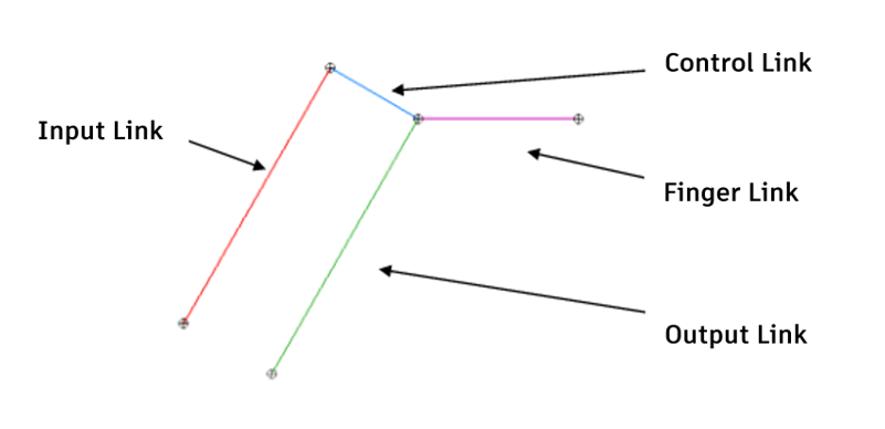
The nomenclature of the four-bar linkage.
Gripper design Scenario
To begin designing the robot gripper, we set some clear criteria. Using the basic info below, we planned to work through the definition, simulation, and optimization of a robotic gripper.
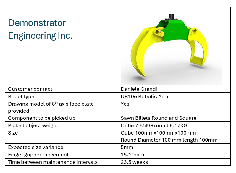
We challenged ourselves with going from design requirements to a manufactured artifact to test internal research for simulation and optimization capabilities along the way.
Challenges with designing with research prototypes
The difficulties of alpha testing a fragmented workflow of research tools this early in its development cannot be understated. It hangs together by a thread, as typically there is only a single set of button clicks that will result in success. The results may not be bugs but featurettes responding in ways the developers aren’t expecting as they input data differently. There can be multiple versions of the software as bugs are fixed as quickly as possible by the development team, and a quick tutorial from the development team may be all the instructions for how to use the software. Moreover, with AI-driven tools, determining whether the output is plausible or a hallucination requires careful evaluation.
After taking time to understand these novel research modules and tether a workflow between them, it was clear that a path forward was possible. Now that we had a defined design scenario, the workflow could be broken down and tested as separate building blocks. If things went to plan, we would have a gripper that could be manufactured and thus tested for function.
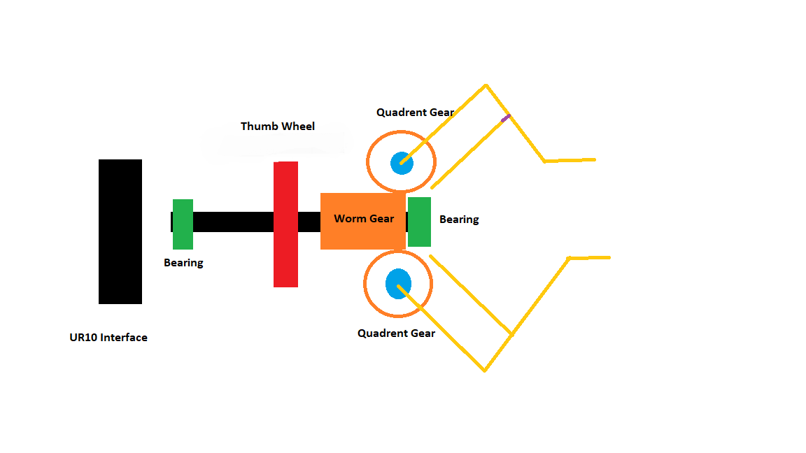
Schematic of the robotic gripper model.
Gripper Arm Definition
From the specification we knew the size of the object that we wanted to pick up and the amount of movement the robot gripper jaws needed to go through (Its open and closed sizes). We had developed a tool that could optimize a 2D wireframe model to define the optimum sizes for each of the parts of the four-bar linkage (Input link, output link, control link, and the fingertip length).
When initially trialing the software, the tool produced some very strange results. Much of this was traced back to the development team working in meters and us in millimeters—another hazard of alpha testing.
Overcoming this, along with repeatability issues and crashes, we eventually could produce a set of data to act as the building block to turn the 2D stick model into a full 3D model.
Producing a 3D model
Going from a 2D wireframe model to a basic 3D model required the definition of the sizes of each link and the size of each linking pin. A parametric optimization allowed us to produce an initial working kinematic solution of the arm, while minimizing volume and strain energy.
To enable actuation by a worm wheel, we grafted a gear onto the end of the arm. Applying the “break fast, fix faster” methodology, we encountered some unexpected results early in the process, but ultimately achieved an acceptable outcome that met all design requirements. We positioned the gear based on the anticipated centerline of the lower pins, which in turn allowed us to define the center position of the worm wheel. For this initial setup, we implemented a simple hand wheel actuation mechanism, removing the need for electronics. The final design step involved the topology optimization of the links, leading to a more lightweight solution.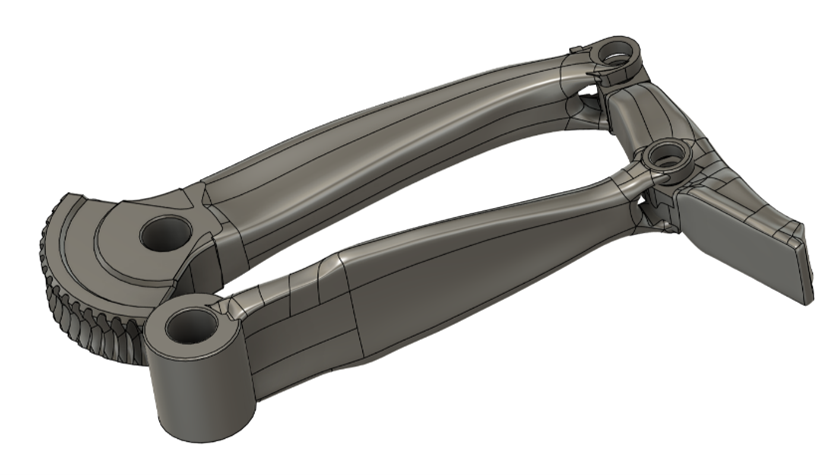
Manufacturing considerations
Following the design process, we began critically evaluating its manufacturability and we needed a way to better test our prototyping concerns.
Enter the Autodesk Technology Centers. Our Technology Centers are wildly capable facilities, outfitted with some of the latest and greatest industrial design and manufacturing technology. We leveraged these facilities and in-house expertise to build our prototype.
We knew we wanted to 3D print and potentially machine the resulting geometry from the design scenario, but this wasn’t enough – we wanted to integrate some off-the-shelf components into the design.
This forced us into new territory, and we encountered a slew of challenges. In part many of these stemmed from our optimized geometry being in mesh form. Meshes have many limitations:
- How can we use a mesh to gauge tolerances with off-the-shelf components?
- How do these off-the-shelf components affect our system motion?
- How do we productively manipulate our mesh to improve assembly?
- How do we convert a mesh to a more manufacturable format?
While some of these challenges are well-known across industries and we probably could have perceived them with enough forethought, it wasn’t until we forced ourselves into a state of prototyping that we fully gauged the impact of these in using our research tools.
These insights gave us new ideas and new requirements as we pursued the next generation of our research tools.
Conclusion
Bringing value to a business through research is highly nuanced. Research can bridge technology gaps, and bring ideas closer to market, but this relationship is not linear. Referring to the TRLs, distinct value can be brought to each stage through rapid demonstration of a novel technology and highlight how innovation can occur while minimizing risk:
- TRL 2 – Technology Concept
- Challenges: No hardware/software, high flaw risk, undefined requirements.
- Value: Spots emerging tech for customer needs or differentiation.
- TRL 3 – Proof of Concept
- Challenges: Fragile prototypes, repeatability, interface, reliability, undefined requirements.
- Value: Finds flaws early, cuts risk, builds brand.
- TRL 4 – Controlled Validation
- Challenges: Limited testing, integration unseen, minimal UI, reliability, undefined requirements.
- Value: Ensures robust performance, enables patents, builds expertise.
In the end, a design that never leaves the screen is like a story that never leaves the page. It may be complete in form, but its impact is never felt. Only when ideas are tested, shared, and applied do they truly come to lifeThe inputs of a research prototype can only be validated and the TRL value captured through retrospection, and that retrospection comes from bringing the prototype through to completion. For us, this meant manufacturing this assembly and physically validating our understanding of it.
By building physical artifacts early in the research process, we can put emerging technologies through real-world stress tests long before they ever reach product. This approach helps us uncover issues, build trust in the tools we’re developing, and ultimately deliver better outcomes for our customers.
If you’re working with complex assemblies, designing consumer products, or exploring system modelling, we’d love to hear from you. What challenges are you facing? What’s holding you back? Your insights help shape the future of our research and the tools we build together.
Get in touch
Have we piqued your interest? Get in touch if you’d like to learn more about Autodesk Research, our projects, people, and potential collaboration opportunities
Contact us